32-Bit CPU (Circuit Simulation)
A computer built inside a circuit simulation environment during CS 2200 (Systems and Networks)
Start: January 2025 • End: February 2025
A computer built inside a circuit simulation environment during CS 2200 (Systems and Networks)
Start: January 2025 • End: February 2025
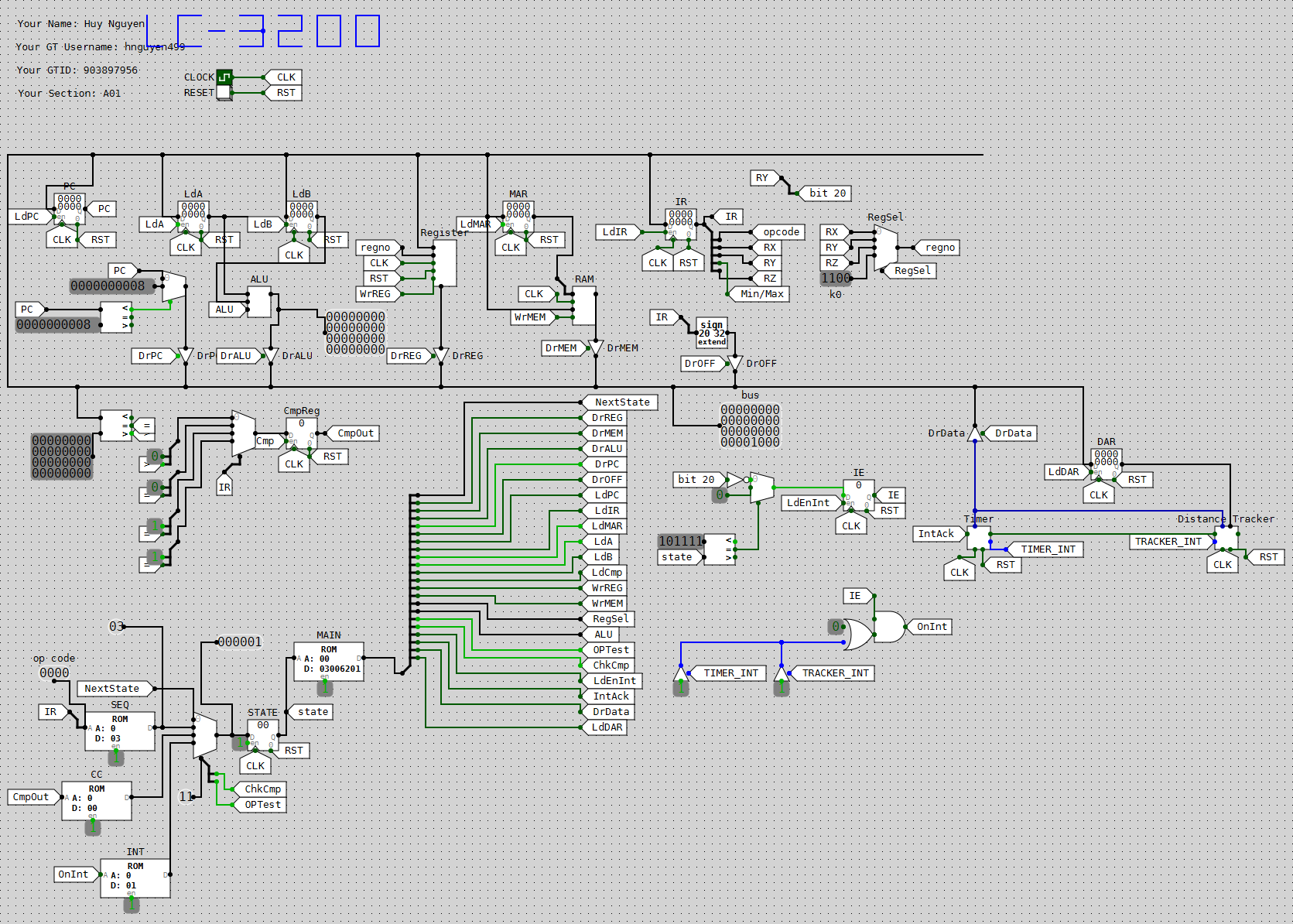
I built a working computer/CPU inside a circuit simulation environment for CS 2200 (Systems & Networks). This computer is fully operatable using assembly instructions from the LC-2200 ISA (based on MIPS) and is capable of handling interrupts from external devices. The computer uses the Von Neumann Architecture where computer instructions and data are not physically separated.
1) Creating the Basic Datapath. Because the circuit simulation software had registers as components, the first step was creating the basic components such as the instruction register, program counter, and register file. The circuit sim allowed for the creation of 'sub-circuits', or separate circuit files that allow us to represent circuits as a block. The ALU, for instance, was composed of a multiplexor connected to simple operators such as a 32-bit adder or a 32-bit inverter.
1) Creating the Basic Datapath. Because the circuit simulation software had registers as components, the first step was creating the basic components such as the instruction register, program counter, and register file. The circuit sim allowed for the creation of 'sub-circuits', or seperate circuit files that allow us to represent circuits as a block. The ALU, for instance, was composed of a multiplexor connected to simple operators such as a 32-bit adder or a 32-bit inverter.
2) Implementing the Microcontrol Unit. The microcontrol unit was implemented using a 4-ROM controller system: a main ROM which outputs the control signals, a sequencer ROM that helps determine which microstate to got o at the end of the FETCH state, condition ROM which helps determine whether or not to branch, and interrupt ROM to determine whether we enter the interrupt macrostate.
3) Writing the Microcode. Using an excel sheet, the microcode for each assembly instruction determined which signals were asserted by an instruction at a given state. The sheet would compile into hexadecimal which could be entered into the microcontrol unit.
4) Adding Interrupt Handling. When adding interrupt handling, an additional ROM had to be added to the microcontroller system and a new register had to be added to indicate whether or not interrupts were enabled. Upon servicing an interrupt, interrupts must disabled until the current state is stored on the stack.
Challenge: Debugging on a circuit simulation is extremely tedious. While testing the instructions on the datapath, I noticed the register outputs were appearing with random numbers instead of the hexadecimal numbers I was expecting.
Solution: I traced through the instructions step-by-step until I discovered a single wire was short-circuiting due to an incorrectly placed connection.